")
")
New processing environment and interactive applications
 Simplified batch jobs coding
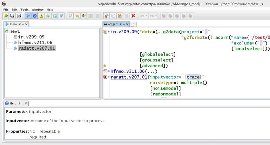
The new batch jobs coding interface is an intuitive environment with step-by-step instructions and built-in help for quick parameter checking. In a single window, you can select the names of input data sets and check for the availability of output data. It goes well with the new WEB job manager.
Thanks to the encoding area with step-by-step nstructions and explicit default parameters set up, jobs can be generated easily and quickly.
 Managing production operations based on WEB
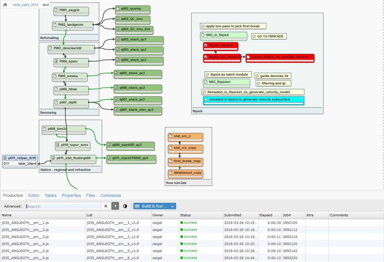
Geophysicists now can submit multiple jobs at a time, as well as quickly select and resubmit any jobs. Users can assign the required number of computing cores with a simple operation.
The job manager based on a web-technology offers a simplified cross-platform instrument for job submission and a faster browser for data being processed.
Automated job submission helps to minimize project execution time.
Processing and quality control of large amounts of data
The new software architecture is optimized for working with data with high fold cover and density of observations in thousands of square kilometers and billions of traces. All available tools have been developed based on feedback from CGG's processing specialists worldwide, and are regularly used in production.
 New approach to quality control
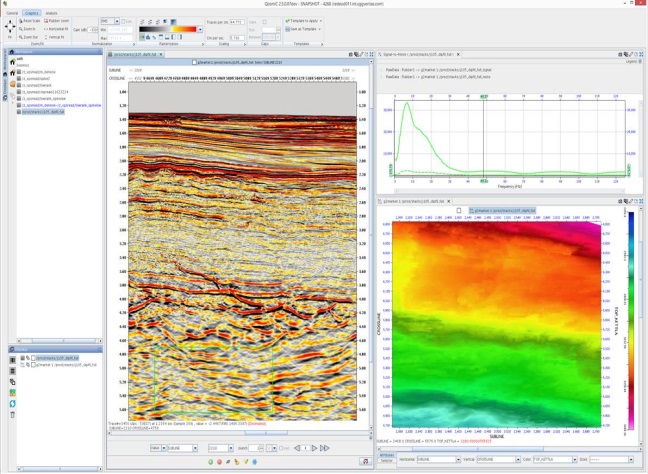
Next-generation interactive tools provide a single interface for a wide range of specialized applications. They include:
- Updating spectra and amplitudes in real time
- Dynamic toolbars
- Interactive connection of different types of data: maps, seismic data and wavelets in one application
- Self-explanatory and responsive interface
 Simple field data input
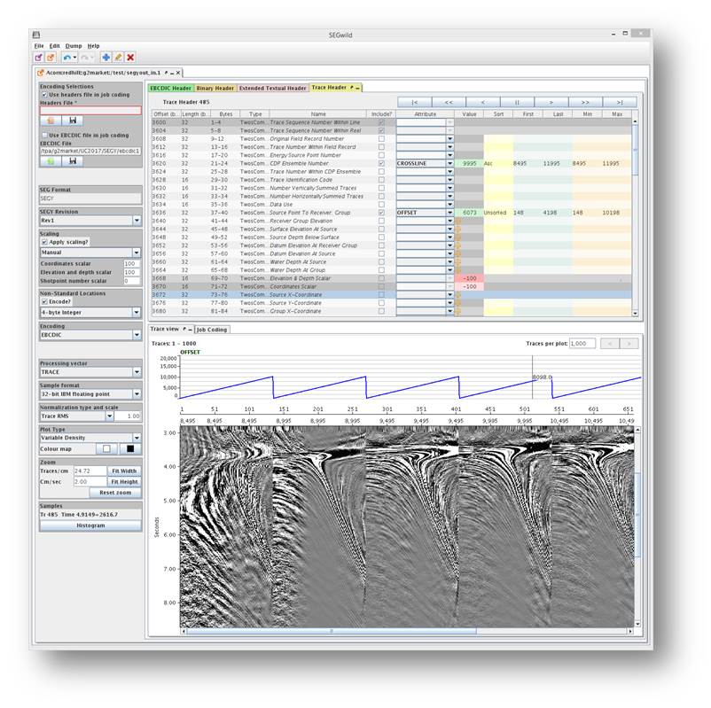
Retrieving and preserving the attributes of seismic traces can be a complex process that requires a lot of time. The new application decodes seismic formats and offers a built-in window for viewing results.
At the end of processing, the SEGY encoding help function reduces the time needed for creation and quality control of the SEGY tape.
Supports all latest formats including SEGD version 3.0 and SEGY version 2.0
First-break picking and trace editing
First break picking is clear and simple: mark the picking direction on the gathers -> set parameters -> start automatic picking. Multiple picking results can be displayed all together to facilitate the selection of the best result. As a subsequent quality control, you can align the seismograms using the picking results.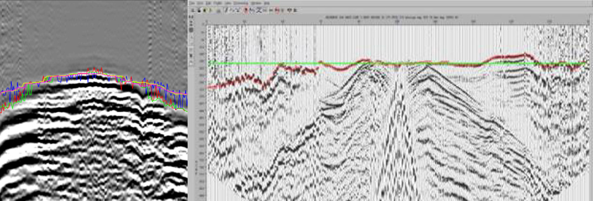
In addition, it is possible to derive a simple near surface model for further work with velocity-depth models.
 Working with near surface statics
The platform for working with the near surface is based on the following components:
- first break picking
- modeling vertical times
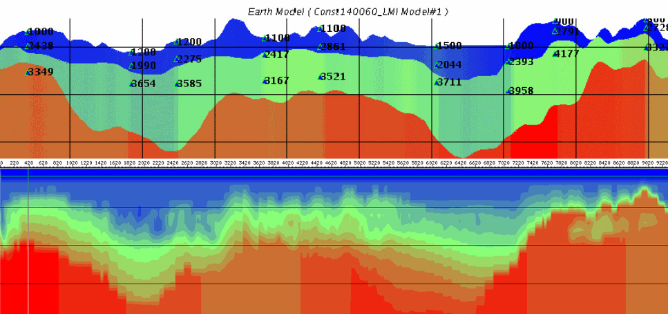
- tomographic near surface model updating works as a separate batch job to minimize the time to create the model, uses all possible vertical times as control points to ensure optimal model tuning.
Input (above) and output (below) tomographic near surface models
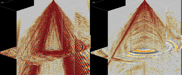
 Velocity model building and 3D visualization
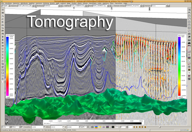
The software developed by CGG for building velocity and depth models is an interactive environment with unique 3D visualization capabilities. The whole process of building a model, from picking, updating velocity and structure, and to visualization, is integrated into one module.
Presented tools are constantly updated and improved; currently, tomographic model updating, defining the aperture, geostatistical analysis and filtering, as well as tools for picking velocities and working with horizons are available.
 Visualization tools allow you to perform 3D quality control of very large data arrays, as well as easily and quickly determine the optimal model. In order to control the quality of signal processing you can calculate and display differences in 3D arrays etc.
An example of a window which shows a seismic volume with velocities applied to straight and curved layers and sections, as well as the surface of horizons and ray paths.
MARINE ACQUISITION TECHNOLOGIES
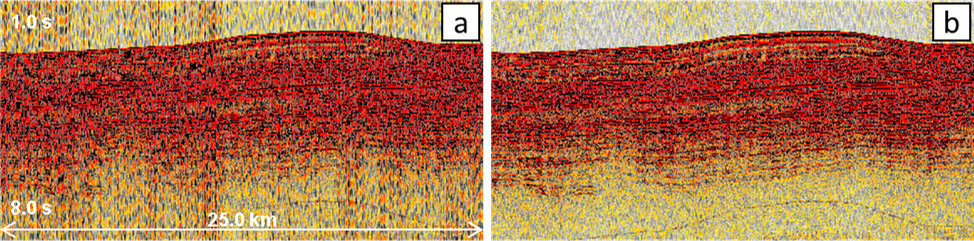
New technology for deghosting
Deghosting provides a more accurate and distinct signal and, thus, a more informative image. Ghost waves can be removed both from the source side and from the receiver side, which leads to an improvement in the frequency and a clearer definition of onsets. Marine seismic surveys with a towed streamer with a variable depth and using BroadSeis technology do not allow for dips in the amplitude spectrum which are possible when conducting studies using standard streamers, and use the full frequency range. Subsequent inversion results benefit from the use of data without ghost waves.
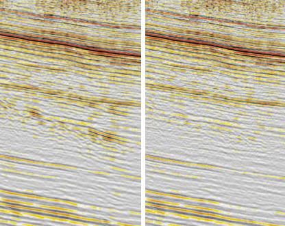
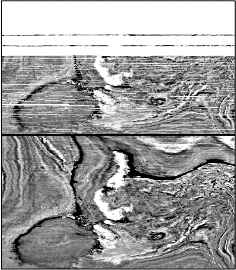
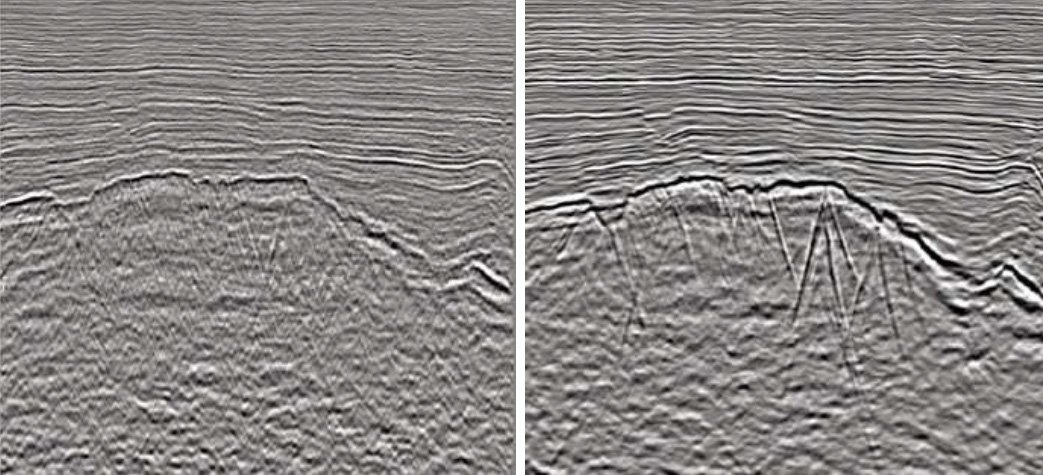
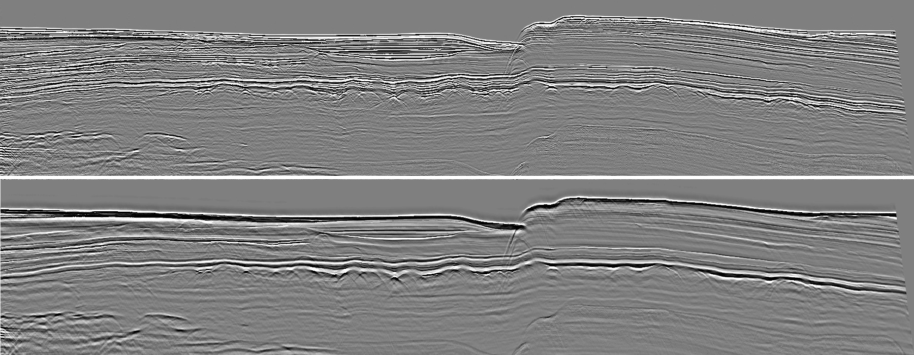 A full stack with a standard signature application (above) and with deghosting (below). The frequency spectrum of the image with deghosting is more informative, especially in the low-frequency area. This allows you to more accurately divide the horizons due to the clear display of the signal.
Sparse dipole tau-P techniques
Using the technique of sparse dipole tau-P conversion allows you to perform a full conversion without losses. This technique can be used to remove seismic interference, attenuate noise, and apply receiver motion corrections.
 Removing seismic interference
Removing seismic interference does not require prior information about the location and speed of the vessel causing the interference. The removal process is effective over the entire frequency range.
Example of source before and after removal of seismic interference
Noise attenuation
The process of sparse dipole noise attenuation gives stable results in the field of source or receiver, and it also works effectively with apparent dipping events, such as swell, or impact noise.
Near-field hydrophone, before (a) and after (b) noise attenuation
LAND ACQUISITION TECHNOLOGIES
 Modeling and attenuating surface noise
The new version of Geovation includes an advanced tool for attenuating surface-related multiples and dispersive interference.
The created noise model is automatically adapted and subtracted from the data in one step without storing the model on disk or in memory.
Before and after surface-related multiples attenuation
 Robust deconvolution and amplitude correction
Surface-consistent processing is now done in one step. Replaces old module sequences and works on the whole survey at once.
This process saves time, avoids edge effects and provides corrections with high resolution.
This approach is iterative, it can be repeated to achieve high resolution.
Static Correction (Monte Carlo)
The approach with the greatest possible surface consistency remains the best method of residual statics/trim-statics. A stochastic solution is used using the global optimization method for the entire survey in one step. This method is applicable to land surveys; shooting with ocean bottom cables, nodal sensors; and in shallow water.
MULTIPLE WAVES and NOISE attenuation
 SRME for land data
Geovation offers a number of modeling algorithms for various multiples, such as attenuation of surface-related and interbed multiples.
In addition to applying SRME to marine data (using convolution), a new technology has been developed for working with land seismic acquisistion data, which allows accurate multiple attenuation in land data.
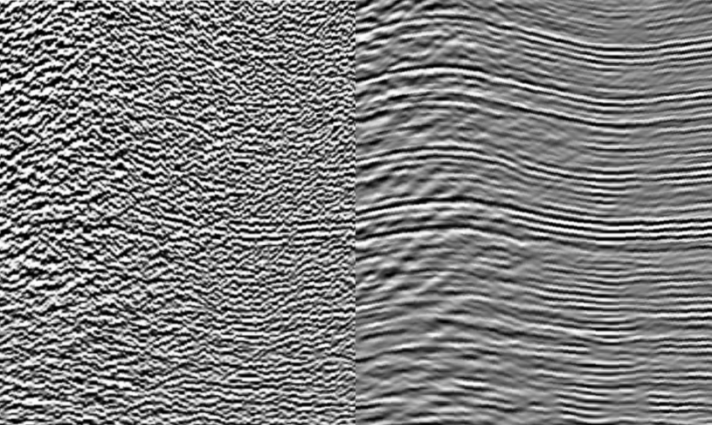
Before and after subtracting the model of multiple waves from the surface in land seismic data
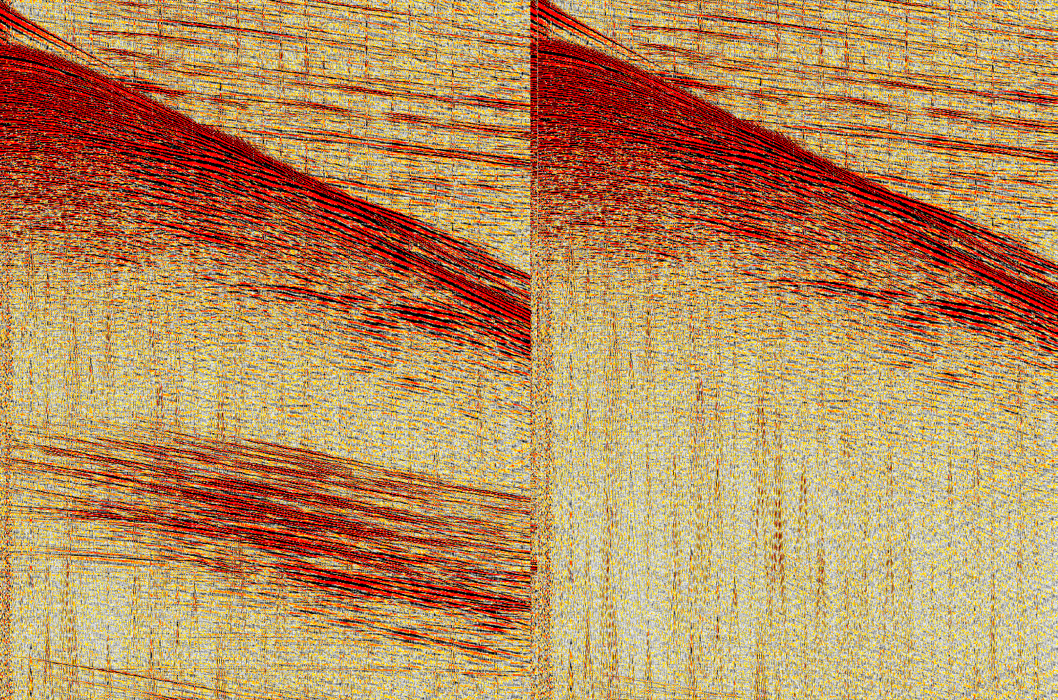
 Subtraction in curvelet domain
In addition to the standard adaptive least squares method subtraction, we also offer subtraction in the curvelet domain to eliminate multiple waves or attenuate noise.
Before and after subtraction in the curvelet domain
 Cascade 3D noise attenuation
CGG offers a new cascade noise attenuation module using various algorithms in a single pass with one Fourier transform. This module is a key module for attenuating noise in the areas of cross-spreads, SP or RP and offsets/COV.
It includes Cadzow algorithm, the coherent interference attenuation algorithm, and many other algorithms.
Central COV before and after attenuation by method of low-level inversion
5D REGULARIZATION
The implemented technology that performs 5D regularization can be used to merge surveys, harmonize folds and regularize azimuths. It provides a “natural” compaction of the input lines of SP and RP for improved migration based on SP. It also offers harmonization of bins/folds/offsets/azimuths.
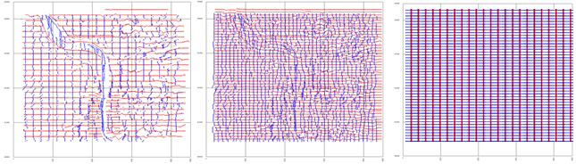
Input map of SP and RP lines (left), 5D interpolation on a given map (center), 5D bin alignment and regularization (right)
 When processing marine narrow-azimuth survey data, 4.5D regularization is used. In this case, the following directions are taken into account: inline, crossline, time, offline, and the azimuth is interpolated taking into account the direction of shooting.
In the case of wide-azimuthal data from land or marine surveys, regularization is performed on arrays of total offsets to maximize the use of the entire range of azimuths obtained.
Near-offset section before (above) and after (below) 4.5D regularization. The empty area in the input data corresponds to the area with other shooting parameters.
TOMOGRAPHY
Nonlinear slope tomography
CGG's patented nonlinear slope tomography technique is a key element in building a velocity model. This method allows you to efficiently convert from time to depth domain as and when necessary, due to the uniformity of format and graphs in both domains.
 High density multilayer tomography
Nonlinear slope tomography in the depth domain gives an opportunity to update layers in any order, any at a time, as well as to perform high resolution tomography in order to obtain even more accurate velocity field of PSDM depth migration in TTI medium.
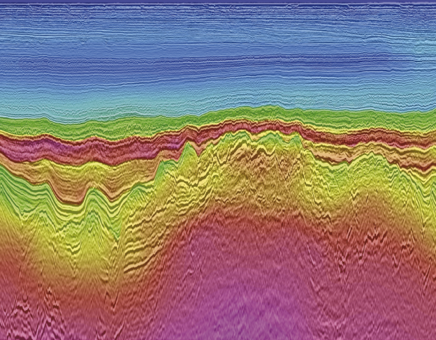
An example of a PSDM section (North Sea) with velocities applied
 Dip-constrained tomography
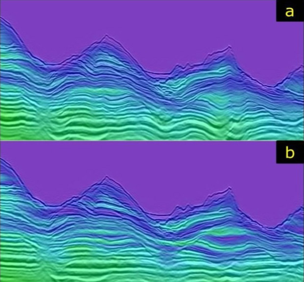
Dip-constrained tomography is applied to complex areas where localized surface waves affect underlying structures. For example, shallow gorges, loose sediments or reefs.
Velocity models applied to the corresponding sections: before (a) and after (b) dip-constrained tomography.
Q-tomography
In addition to the velocity, delta and epsilon parameters, Q-tomography can also take into account absorption in a complex inversion. This method uses additional Q calculation information from seismograms.
MIGRATION
Q KIRCHHOFF migration
The developed algorithms include standard Kirchhoff migration in the time and depth domains. They are excellently and effectively implemented in the process of tomographic refinement.
The new implementation of time migration works much faster than the algorithms of the previous generation. Depth migration allows Q-migration.
Controlled Beam Migration
The method is designed to achieve an improved signal-to-noise ratio and display steep dips in difficult geological conditions. This technique is a powerful and versatile tool that allows you to perform a deeper structural interpretation used to accelerate the construction of a velocity model in complex areas, such as in the subsalt section of a slice. The ability of this tool to display such structures as overthrusts and cavities in the bedding rock makes it extremely valuable in terms of accurate mapping of complex geological structures. This, in addition, gives excellent results when working with typical land datasets containing a lot of interference.
Also, an option of multiple waves attenuation was added to the technique, which allows recognition of internal multiple waves. This option has particularly proved its worth in areas such as the North Sea, where significant multiple generators are observed.
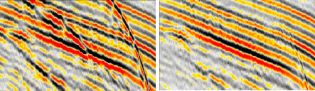
Comparison of the display of sharply inclined faults/faults in a granite bedrock using Kirchhoff migration (left) and controlled beam migration (right).
Reverse time migration
The method calculates the wave propagation in the downward and upward directions through the entire model of a geological environment, visually characterizing the refracted waves and other complex ray paths. In many cases, the ability to use such complex types of waves allows you to display parts of the geological environment which in other cases have poor direct illumination in the section.
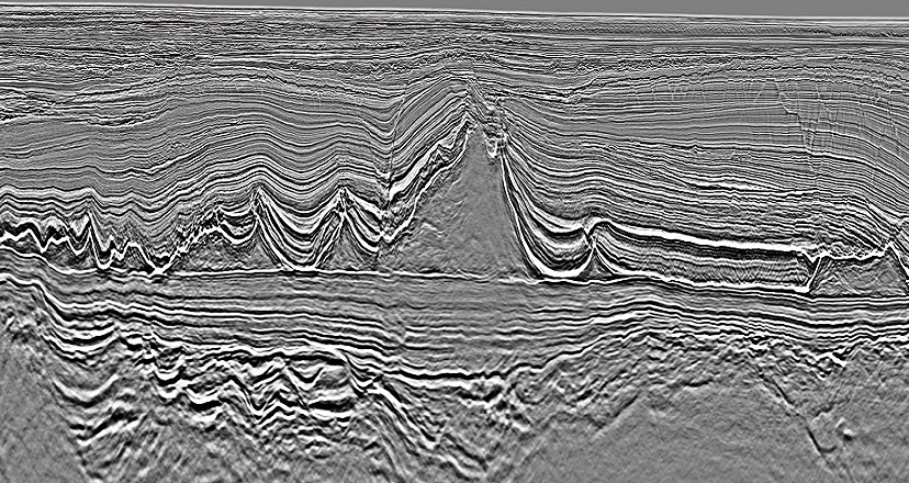
Structurally complex geological environment shown using the reverse time migration technique
Conclusion
The Geovation 2 software developed by CGG has moved to a new platform to solve complex problems when working with increasing volumes of seismic data.
The new version of Geovation 2 includes tools for operational processing of dense, wide-azimuth data with high fold cover, both in terms of computation and data quality control. The code for most modern algorithms has been optimized to speed up the production cycle.
The module coding interface allows geophysicists to more effectively optimize the results, and thus receive more information about the geological structure.
The technological component of Geovation 2 offers solutions for all processing conditions and geological environments. Technologies added in the latest version include solutions for building a more accurate model, advanced solutions and interference attenuation toolsets to improve the display of the geological environment.
Worldwide Headquarters
Paris (France) +33 1 64 47 45 00
Massy (France) +33 1 64 47 30 00
Houston (USA) +1 832 351 8300
Exclusive distributor in Russia
Moscow, +7 495 982 36 31
Tyumen, +7 345 231 56 07 info@geoleader.org